De0NanoExtension : Différence entre versions
| Ligne 3 : | Ligne 3 : | ||
==={{Vert|Présentation du projet}}=== | ==={{Vert|Présentation du projet}}=== | ||
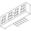
Le but de ce projet est de réaliser un shield multifonction, généraliste, sur une De0Nano. Les composants qui vont être utilisés sont un afficheur 4x7 segments, un bouton à codage rotatif, 2 registres à décalage (74HC595), des boutons poussoirs et des leds. | Le but de ce projet est de réaliser un shield multifonction, généraliste, sur une De0Nano. Les composants qui vont être utilisés sont un afficheur 4x7 segments, un bouton à codage rotatif, 2 registres à décalage (74HC595), des boutons poussoirs et des leds. | ||
| + | |||
| + | |||
| + | |||
| + | |||
| + | |||
[[Fichier:Afficheur4x7.jpg|100px|link=Fichier:Afficheur4x7.jpg]] | [[Fichier:Afficheur4x7.jpg|100px|link=Fichier:Afficheur4x7.jpg]] | ||
==={{Vert|Conception du schéma Eagle}}=== | ==={{Vert|Conception du schéma Eagle}}=== | ||
Version du 19 janvier 2017 à 14:38
Sommaire
Projet carte extension pour DE0Nano 2016/2017 (Violette et Villaire)
Première Partie : Étude théorique
Présentation du projet
Le but de ce projet est de réaliser un shield multifonction, généraliste, sur une De0Nano. Les composants qui vont être utilisés sont un afficheur 4x7 segments, un bouton à codage rotatif, 2 registres à décalage (74HC595), des boutons poussoirs et des leds.
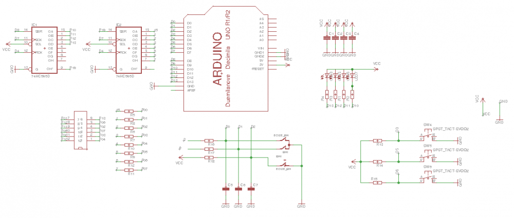
Conception du schéma Eagle
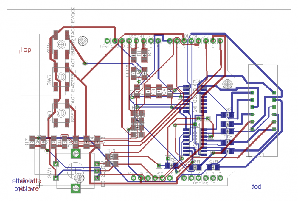
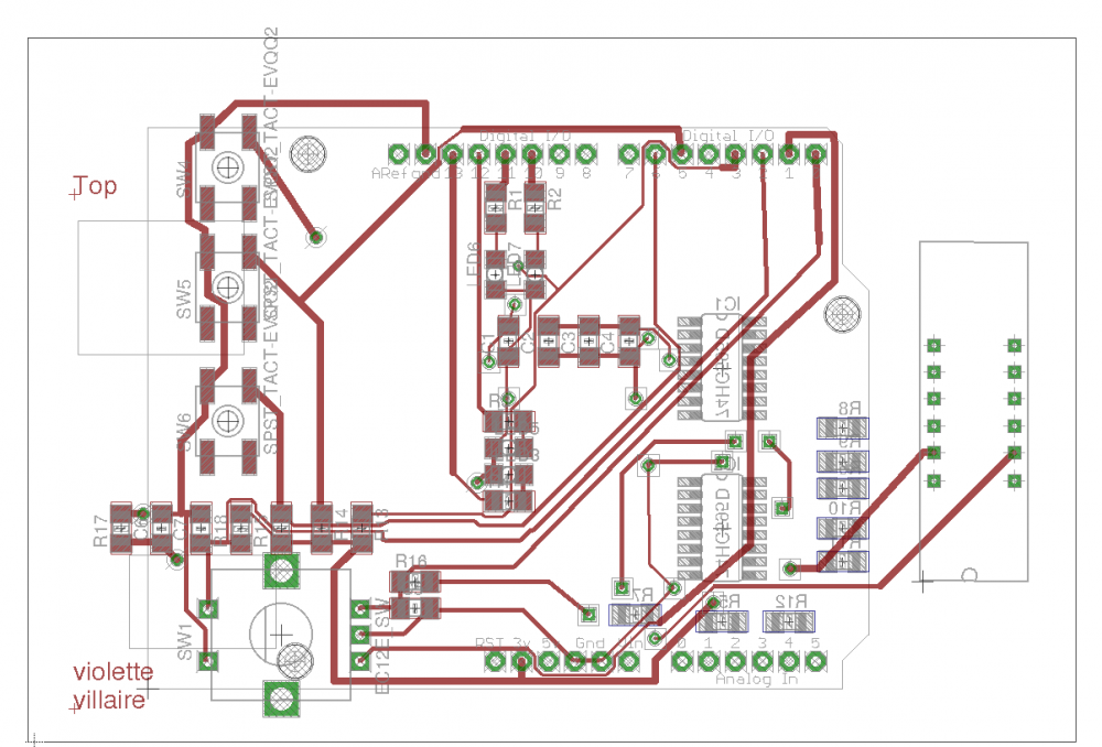
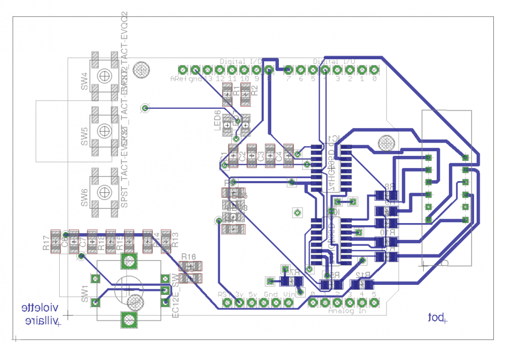
Conception du routage Eagle
Modèle:Routage complet
Modèle:Routage de la face Top
Modèle:Routage de la face Bot
Deuxième Partie : Réalisation de la carte
Troisième Partie : Test de la carte
Test des leds
const int L1 = 10; //Déclaration des broches
const int L2 = 11;
const int L3 = 12;
const int L4 = 13;

void setup()
{
  pinMode(L1, OUTPUT); //Les broches sont des broches de sortie
  pinMode(L2, OUTPUT);
  pinMode(L3, OUTPUT);
  pinMode(L4, OUTPUT);
}
void loop()
{

  digitalWrite(L1, HIGH); //Toutes les leds s'allument pendant 1 seconde
  digitalWrite(L2, HIGH);
  digitalWrite(L3, HIGH);
  digitalWrite(L4, HIGH);
  delay(1000);
  digitalWrite(L1, LOW);
  digitalWrite(L2, LOW);
  digitalWrite(L3, LOW);
  digitalWrite(L4, LOW);
  delay(1000);

}
Test des boutons poussoirs
int pinBouton;
int pinBouton2;
int pinBouton3;
int pinLed1, pinLed2, pinLed3; //Déclaration des variables

void setup()
{
  pinBouton = 3;
  pinBouton2 = 5;
  pinBouton3 = 6;

  pinLed1 = 10;
  pinLed2 = 11;
  pinLed3 = 12; //Initialisation des variables


  pinMode(pinBouton, INPUT); //Mode lecture pour les boutons
  pinMode(pinBouton2, INPUT);
  pinMode(pinBouton3, INPUT);

  pinMode(pinLed1, OUTPUT); //Mode écriture pour les leds
  pinMode(pinLed2, OUTPUT);
  pinMode(pinLed3, OUTPUT);
}

void loop()
{


  boolean etatBouton = digitalRead(pinBouton);
  boolean etatBouton2 = digitalRead(pinBouton2);
  boolean etatBouton3 = digitalRead(pinBouton3); //Lecture de l'état du bouton et stockage dans etatBouton

  if (etatBouton==LOW) //Test si bouton appuyé
  {
    digitalWrite(pinLed1,LOW);   //led1 allumée
    digitalWrite(pinLed2,HIGH); //led2 éteinte
    digitalWrite(pinLed3,HIGH);//led3 éteinte
  }

  if (etatBouton2==LOW) //Test si bouton2 appuyé

  {
    digitalWrite(pinLed1,HIGH);  //led1 éteinte
    digitalWrite(pinLed2,LOW);  //led2 allumée
    digitalWrite(pinLed3,HIGH);//led3 éteinte
  }

   if (etatBouton3==LOW) //Test si bouton3 appuyé

  {
    digitalWrite(pinLed1,HIGH); //led1 éteinte
    digitalWrite(pinLed2,HIGH);//led2 éteinte
    digitalWrite(pinLed3,LOW);//led3 allumée
  }


}
Quatrième Partie : Réalisation d'un programme
Nous avons décidé de tester la carte avec une carte Arduino UNO. Le programme utilisé est :
/* Define shift register pins used for seven segment display */
#define LATCH_DIO 4
#define CLK_DIO 7
#define DATA_DIO 8

/* Segment byte maps for numbers 0 to 9 */
const byte SEGMENT_MAP[] = {
  0xC0,0xF9,0xA4,0xB0,0x99,0x92,0x82,0xF8,0X80,0X90};
/* Byte maps to select digit 1 to 4 */
const byte SEGMENT_SELECT[] = {0xF1,0xF2,0xF4,0xF8};

byte x=0;
byte x1=0;
byte x2=0;
byte x3=0;

#define PinA 1    //  1ere sortie du codeur
#define PinB 0    //  2e sortie du codeur

volatile boolean mouvement;
volatile boolean up;

unsigned int valeur = 0;

// routine déclanchée quand le signal A passe de haut a bas


void setup ()
{
  /* Set DIO pins to outputs */
  pinMode(LATCH_DIO,OUTPUT);
  pinMode(CLK_DIO,OUTPUT);
  pinMode(DATA_DIO,OUTPUT);

  pinMode(PinA,INPUT);
  pinMode(PinB,INPUT);

  // activation des pullups internes de l'Arduino, si on n'utilise pas de pullups externes.
  //  digitalWrite (PinA, HIGH);
  //  digitalWrite (PinB, HIGH);

  attachInterrupt (0,routineInterruption,FALLING);   // interruption sur front descendant

  Serial.begin (9600);   // initialisation du moniteur série
  Serial.println("Veuillez tourner le bouton");
}

void routineInterruption ()  {
  //if (digitalRead(PinA))
    up = digitalRead(PinA);

  //  else
  //  up = !digitalRead(PinB);
  mouvement = true;
}


/* Main program */
void loop()
{

  /* Update the display with the current counter value */


  if (mouvement)  {		  // on a détecté une rotation du bouton
    if (up)
      //valeur++;
      incrementBCD(&valeur);
    else
      //valeur--;
      decrementBCD(&valeur);
    mouvement= false;

    Serial.println (valeur);

  }

  WriteNumberToSegment(0 , (valeur&0xF000)>>12);
    delay(1);
    WriteNumberToSegment(1 , (valeur&0x0F00)>>8);
    delay(1);
    WriteNumberToSegment(2 , (valeur&0x00F0)>>4);
    delay(1);
    WriteNumberToSegment(3 , (valeur&0x000F));
    delay(1);
}

/* Write a decimal number between 0 and 9 to one of the 4 digits of the display */
void WriteNumberToSegment(byte Segment, byte Value)
{
  digitalWrite(LATCH_DIO,LOW);
  shiftOut(DATA_DIO, CLK_DIO, MSBFIRST, SEGMENT_MAP[Value]);
  shiftOut(DATA_DIO, CLK_DIO, MSBFIRST, SEGMENT_SELECT[Segment] );
  digitalWrite(LATCH_DIO,HIGH);
}

void incrementBCD(unsigned int *cnt) {
  (*cnt)++;
  if ((*cnt & 0x000F) > 0x0009) *cnt += 6;
  if ((*cnt & 0x00F0) > 0x0090) *cnt += 0x0060;
  if ((*cnt & 0x0F00) > 0x0900) *cnt += 0x0600;
  if ((*cnt & 0xF000) > 0x9000) *cnt += 0x6000;
}

void decrementBCD(unsigned int *cnt) {
  (*cnt)--;
  if ((*cnt & 0x000F) == 0x000F) *cnt -= 6;
  if ((*cnt & 0x00F0) == 0x00F0) *cnt -= 0x0060;
  if ((*cnt & 0x0F00) == 0x0F00) *cnt -= 0x0600;
  if ((*cnt & 0xF000) == 0xF000) *cnt -= 0x6000;
}
